C Purlin Span Guide: A Comprehensive Overview (Updated 03/26/2026)
This guide details C purlin spans, referencing load tables based on Span/180 deflection limits and ultimate load capacities.
Flexospan CEES members and STRAMIT purlins are covered.
C Purlins are crucial components in modern steel building construction, providing essential support for roof and wall cladding. They are cold-formed light gauge steel structural members, known for their cost-effectiveness and ease of installation. Understanding their capabilities, particularly concerning span, is vital for safe and efficient building design. This guide focuses on C purlin span considerations, offering a comprehensive overview for professionals and enthusiasts alike.
Properly calculating and implementing C purlin spans ensures structural integrity, preventing deflection and potential failure under various loads. Factors like material grade, purlin gauge, span length, and loading conditions all play a significant role. Utilizing span tables and adhering to deflection limits, such as the commonly applied Span/180 rule, are fundamental to successful implementation. Furthermore, incorporating elements like sag bars and bridging significantly enhances the stability and performance of C purlin systems.
This introduction sets the stage for a detailed exploration of C purlin spans, covering design considerations, specific product systems like Flexospan and STRAMIT, and essential installation practices.
What are C Purlins?
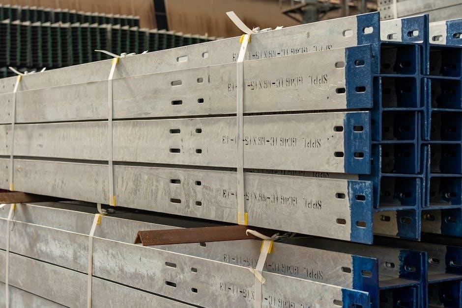
C Purlins are cold-formed steel structural members with a distinctive “C” shape, widely utilized as horizontal support members in roof and wall framing systems. They are manufactured from thin gauge steel sheets, offering a high strength-to-weight ratio, making them an economical choice for various building applications. These members efficiently transfer loads from the roof or wall cladding to the main supporting frames, like columns or rafters.
Unlike traditional hot-rolled steel, C purlins are produced through a cold-forming process, which involves shaping the steel at room temperature. This process enhances the steel’s yield strength and provides a consistent, precise profile. Common materials include galvanized steel, offering corrosion resistance. They are available in various sizes and gauges, allowing for customization based on specific project requirements and load demands.
C Purlins, alongside C girts, are integral to systems like those offered by Flexospan and STRAMIT, providing robust and reliable structural support.
Common Applications of C Purlins
C Purlins find extensive use across a diverse range of building projects, primarily serving as essential components in roof and wall framing. Agricultural buildings, industrial warehouses, and commercial structures frequently employ C purlins due to their cost-effectiveness and structural efficiency. Garages and workshops, like those constructed with Z purlins spanning 20ft with sag bars, also benefit from their application.
They are particularly well-suited for projects requiring long spans and light-weight construction. C Purlins effectively support various cladding materials, including metal roofing sheets, wall panels, and insulation. Systems like Flexospan CEES utilize C purlins and girts for both roof and wall applications, providing complete structural solutions.
STRAMIT purlins demonstrate their versatility in diverse projects, while Even-profile C purlins offer consistent performance. Their adaptability makes them a staple in modern construction practices.

Factors Affecting C Purlin Span
Several factors influence C purlin span, including material grade, purlin gauge (thickness), span length, loading types (dead & live), and wind load considerations.
Material Grade and Strength
The material grade of the steel used in C purlins is a primary determinant of their span capabilities. Higher-strength steel allows for longer spans with the same purlin size, or smaller purlin sizes for a given span. Common steel grades used in C purlin manufacturing possess varying yield and tensile strengths, directly impacting load-bearing capacity.
Understanding the specific steel grade is crucial for accurate span calculations. Manufacturers provide material specifications, detailing the yield strength (the point at which the steel begins to deform permanently) and tensile strength (the maximum stress the steel can withstand before breaking). These values are essential inputs for engineering calculations and span table interpretations.
Furthermore, the consistency of the material is vital. Variations in steel quality can compromise structural integrity. Reputable manufacturers adhere to strict quality control standards to ensure consistent material properties throughout each batch of C purlins, guaranteeing predictable performance and reliable span lengths. Selecting the appropriate grade is paramount for safety and cost-effectiveness.
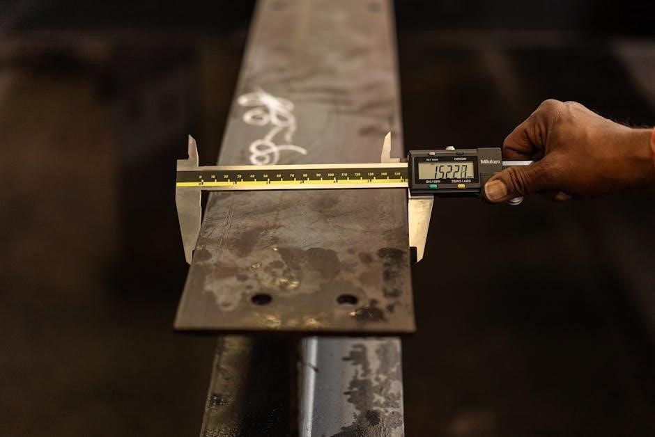
Purlin Gauge (Thickness)
The gauge, or thickness, of the steel used in a C purlin’s construction significantly influences its load-bearing capacity and, consequently, its allowable span. Thicker gauges provide greater resistance to bending and buckling, enabling longer spans. Conversely, thinner gauges are suitable for shorter spans and lighter loads, offering a more economical solution.
Purlin gauge is typically measured in millimeters (mm) or gauge numbers, with lower gauge numbers indicating thicker steel. Selecting the appropriate gauge involves balancing cost considerations with structural requirements. Increasing the gauge increases material costs but enhances strength and stiffness.
Span tables provided by manufacturers categorize purlins based on their gauge; These tables clearly indicate the maximum allowable span for each gauge under various loading conditions. Careful consideration of the anticipated loads – dead, live, and wind – is essential when determining the appropriate gauge for a specific application. Proper gauge selection ensures structural integrity and prevents premature failure.
Span Length and Support Conditions
The span length – the distance between supports – is a primary determinant of a C purlin’s capacity. Longer spans necessitate heavier gauges or closer purlin spacing to maintain structural integrity. Support conditions also play a crucial role; simply supported spans, common in many applications, have different load-carrying capabilities than continuous spans.
Continuous spans, where the purlin extends over multiple supports, generally allow for longer spans due to the distribution of loads. However, accurately calculating the load distribution requires careful engineering analysis. End bay and inward bay configurations impact capacity, as noted in STRAMIT purlin documentation, with inward bays often exhibiting higher load capacities.
Reduced end spans, where the end bays are shorter, can also influence the overall system performance. Proper detailing and consideration of these support conditions are vital for safe and efficient C purlin system design, ensuring compliance with deflection limits like Span/180.
Loading Types: Dead Load vs. Live Load
Understanding the distinction between dead and live loads is fundamental to accurate C purlin span calculations. Dead load encompasses the permanent weight of the roof sheeting, purlins themselves, and any fixed components like insulation. Live load, conversely, represents variable forces – snow, wind, and maintenance personnel – that act upon the structure.
Load tables, such as those provided by STRAMIT, typically present unfactored gravity load capacities. These must be adjusted using appropriate load factors to account for both dead and live loads, ensuring a margin of safety. Wind load considerations are particularly critical, especially for longer spans, and require separate analysis.
Accurate assessment of both dead and live loads is paramount. Underestimating live loads, particularly snow or wind, can lead to structural failure. Conversely, overestimating loads results in unnecessarily expensive designs. A balanced approach, guided by building codes and engineering principles, is essential.
Wind Load Considerations
Wind load is a significant factor in C purlin span design, particularly for buildings in exposed locations. It manifests as both positive (uplift) and negative (downward) pressure, demanding careful evaluation. Uplift forces attempt to lift the roof sheeting and purlins, while downward forces add to the overall load.
STRAMIT product technical manuals detail ultimate load capacities specifically for wind uplift, alongside gravity loads. These capacities are crucial for determining safe spans. Wind load calculations depend on factors like wind speed, building height, terrain category, and roof angle.

Proper bracing and secure connections are vital to resist wind forces. Bridging, especially in end bays, significantly enhances wind resistance. Reduced end spans can also mitigate uplift pressures. Consulting local building codes and a qualified structural engineer is highly recommended to ensure adequate wind load resistance in your C purlin system.

Calculating C Purlin Span
Span calculations utilize span tables, considering deflection limits (Span/180) and ultimate/working load capacities. Accurate determination ensures structural integrity and safety.
Span Tables and Their Usage
Span tables are fundamental tools for determining appropriate C purlin spans, offering pre-calculated load capacities based on various factors. These tables, readily available through resources like Google and product-specific manuals (such as STRAMIT Purlins technical documentation), provide unfactored gravity load capacities. These capacities are determined by the lesser of the purlin’s working load capacity or a deflection limit, commonly set at Span/180.
Understanding how to interpret these tables is crucial. They typically categorize spans based on purlin gauge (thickness), material grade, and support conditions. Users must carefully select the table corresponding to their specific purlin characteristics and intended application. Furthermore, span tables often differentiate between outward and inward bay spans, acknowledging the differing load distributions.
For instance, STRAMIT documentation highlights the need to consult Table 5b for inward bay capacities and specifies two rows of bridging for end bays, demonstrating the importance of considering bay location. Always verify the table’s applicability to your project’s specific requirements before proceeding with design or installation.
Deflection Limits (Span/180)
The Span/180 deflection limit is a widely adopted criterion in C purlin design, representing the maximum allowable deflection as a fraction of the span length. This standard ensures structural integrity and prevents issues like ponding water on roofs or damage to attached elements. Load tables frequently utilize this limit to determine permissible spans, prioritizing stiffness alongside load-bearing capacity.

Essentially, a span of 180 inches allows for a maximum deflection of one inch. Exceeding this limit can compromise the building’s performance and longevity. Calculations involving deflection consider factors like material properties, purlin geometry, and applied loads (dead and live).
Span tables provide convenient pre-calculated values adhering to this criterion, simplifying the design process. However, it’s crucial to understand that Span/180 is a common, but not absolute, limit; specific project requirements or local building codes may necessitate more stringent deflection criteria. Always verify compliance with all applicable regulations.
Ultimate Load Capacities
Ultimate load capacities represent the maximum load a C purlin can withstand before failure, encompassing both gravity and wind forces. These values are crucial for ensuring structural safety and preventing catastrophic collapse. Load tables, like those provided by STRAMIT, detail these capacities for various purlin sizes and span configurations.
Understanding ultimate load capacity involves considering both bending and shear stresses within the purlin section. Gravity loads contribute to bending, while wind uplift forces can induce both bending and shear. Tables often present separate ultimate capacities for outward and inward loads, reflecting differing support conditions.
It’s vital to remember that ultimate load capacities are unfactored values. Building codes require applying load factors to account for uncertainties in load estimation and material properties. These factored capacities are then used for design verification, ensuring an adequate margin of safety. Always consult relevant standards and engineering principles.
Working Load Capacity
Working load capacity defines the maximum permissible load a C purlin can safely carry during its intended service life. Unlike ultimate load, it’s determined after applying appropriate load factors to account for uncertainties in load estimations and material strengths. This factored value ensures a robust safety margin against failure.
Load tables, such as those found in product technical manuals like STRAMIT Purlins, provide working load capacities for gravity loads. These are often based on the lesser of the purlin’s calculated working capacity or a deflection limit – commonly Span/180. This ensures both strength and acceptable performance under service loads.
Determining working load capacity requires careful consideration of load combinations, including dead loads, live loads, and wind loads. Engineers must verify that the purlin’s capacity exceeds the factored loads imposed upon it, guaranteeing structural integrity and long-term reliability.

Design Considerations for C Purlin Systems
Effective design involves purlin spacing (like 4ft O.C.), sag bar implementation (every 4ft), bridging for end and inward bays, and reduced end span adjustments.
Purlin Spacing (e.g., 4ft O.C.)
Determining appropriate purlin spacing is crucial for structural integrity and cost-effectiveness. A common practice, as observed in workshop shed constructions, utilizes a 4ft On Center (O.C.) spacing. This spacing provides a balance between support and material usage, effectively distributing loads across the structure. However, optimal spacing isn’t universally fixed and depends heavily on factors like the purlin gauge, material grade, span length, and anticipated loading conditions – both dead and live loads.
Closer spacing, while increasing material costs, offers enhanced support for heavier loads or longer spans. Conversely, wider spacing reduces material requirements but may necessitate thicker gauge purlins to maintain adequate strength and prevent excessive deflection. Careful consideration must be given to wind load implications as well, potentially influencing the required purlin spacing for optimal performance. The 4ft O.C. example serves as a starting point, requiring detailed calculations and adherence to relevant building codes for a safe and reliable design.
Sag Bar Implementation and Spacing (e.g., every 4ft)
Sag bars play a vital role in maintaining the vertical alignment of C purlins, particularly over extended spans. They counteract the tendency of purlins to buckle or distort under load, enhancing overall structural stability. As demonstrated in workshop shed examples, implementing sag bars at intervals of approximately every 4ft is a common and effective practice. This spacing provides sufficient support to prevent unwanted movement and maintain the purlin’s intended profile.
The necessity for sag bars increases with span length and purlin height. They essentially act as intermediate supports, reducing the unbraced length of the purlin and bolstering its resistance to bending. Proper installation is key; sag bars must be securely fastened to both the purlin and supporting structure. While 4ft spacing is a good rule of thumb, specific project requirements and load calculations may necessitate adjustments to this interval for optimal performance and safety.
Bridging Requirements (End Bays & Inward Bays)
Bridging within C purlin systems is crucial for distributing loads and preventing lateral buckling, especially in end bays and inward bays. STRAMIT purlin technical manuals highlight specific bridging requirements based on bay location. Typically, end bays require a more robust bridging solution – often two rows of bridging – to resist concentrated loads and potential instability at the structure’s perimeter.
Inward bays generally require less extensive bridging, often a single row, as they benefit from greater support from adjacent bays. Load tables, like those found in product technical manuals, provide capacity figures (e.g., 3.07 kN/m outwards, 3.04 kN/m inwards) that are directly influenced by the bridging configuration. Correct bridging ensures load transfer efficiency and prevents localized stress concentrations. Always consult relevant tables and specifications to determine the appropriate bridging type and spacing for your specific C purlin system and load conditions.
Reduced End Span Adjustments
Adjustments for reduced end spans are critical in C purlin design, as shorter end bay lengths impact load distribution and capacity. When end bays are reduced in length compared to the standard span, the overall system’s load-bearing capability changes. STRAMIT purlin documentation addresses this, indicating that capacity calculations must account for these variations.
Reduced end spans can potentially increase the load capacity in those specific bays, but a comprehensive assessment is essential. This adjustment affects both gravity loads and wind uplift forces. Load tables often provide specific data for varied end span configurations, allowing engineers to accurately determine the system’s performance. Ignoring these adjustments can lead to underestimation of stresses and potential structural failure. Proper consideration of reduced end spans ensures a safe and efficient C purlin system.

Specific C Purlin Products & Systems
Several manufacturers offer C purlin systems, including Flexospan CEES structural steel, Even-profile C purlins/girts, and STRAMIT purlins, each with unique specifications.
Flexospan CEES Structural Steel Members
Flexospan provides a comprehensive range of Cold Formed Steel (CFS) structural members, specifically CEES (Cut Edge Edge Stiffened) C purlins and girts designed for robust roofing and wall cladding support. These members are manufactured to exacting standards, ensuring consistent quality and performance across various project requirements.
The Flexospan system is known for its versatility, accommodating diverse span lengths and load conditions. Detailed span tables are available, outlining permissible spans based on material gauge, support conditions, and applied loads. These tables consider both dead loads (the weight of the roofing material itself) and live loads (such as snow or wind).
Furthermore, Flexospan emphasizes the importance of proper installation, including accurate alignment and adequate vertical support. Utilizing appropriate bridging, particularly in end bays and inward bays, is crucial for distributing loads effectively and preventing instability. The system’s design allows for adjustments to reduced end spans, optimizing material usage and structural integrity. Flexospan’s technical documentation provides comprehensive guidance for engineers and installers.
Even-Profile C Purlins and C Girts
Even-profile C purlins and C girts represent a widely utilized solution in light-gauge steel framing, offering a balance of strength, economy, and ease of installation. These members are commonly employed in agricultural buildings, industrial sheds, and commercial structures, providing reliable support for roofing and wall cladding systems.
Span capabilities are directly influenced by the purlin gauge (thickness) and the spacing between supports – a typical spacing is 4ft on center (O.C.). Implementing sag bars, spaced approximately every 4ft, is highly recommended to maintain purlin alignment and prevent unwanted deflection under load. This is particularly important for longer spans.

Load tables for even-profile members provide unfactored gravity load capacities, governed by either the working load capacity of the purlin or a deflection limit of Span/180. Ultimate load capacities are also specified for gravity, wind uplift, and deflection criteria. Careful consideration of these factors ensures a structurally sound and durable building envelope.
STRAMIT Purlins: Technical Specifications
STRAMIT Purlins are renowned for their robust design and adherence to stringent quality standards, offering reliable performance in diverse construction applications. Technical documentation, such as product technical manuals, provides comprehensive data regarding load capacities and span limitations. These specifications are crucial for accurate structural design and ensuring building safety.
Load tables detail unfactored gravity load capacities, determined by the lesser of the purlin’s working load capacity or deflection limits – commonly Span/180. Ultimate load capacities are also provided for gravity loads, wind uplift forces, and corresponding deflection criteria.
For inward bays, Table 5b within STRAMIT documentation specifies bridging requirements, often recommending two rows of bridging for end bays and a specific configuration for inward spans. A sample capacity for a STRAMIT purlin run might be 3.07 kN/m outwards and 3.04 kN/m inwards, demonstrating the importance of bay location.

Installation and Support
Proper alignment is key during installation, alongside crucial vertical support. Sag bars, spaced every 4ft, maintain upright alignment, and welding—if needed—requires careful consideration.
Proper Alignment During Installation
Achieving proper alignment during C purlin installation is paramount for structural integrity and long-term performance. Initial setup must prioritize plumbness and levelness across the entire span. Deviations, even minor ones, can compromise load distribution and potentially lead to premature failure. Careful attention should be given to ensuring each purlin is correctly positioned according to the design specifications, particularly regarding spacing – commonly 4ft on center (O.C.).
Temporary bracing is often essential during installation to maintain alignment before permanent connections are secured. This bracing prevents unwanted movement or distortion as subsequent purlins are installed. Utilizing string lines or laser levels can significantly aid in achieving a straight and consistent purlin layout. Furthermore, verifying the alignment of supports – whether they are walls, columns, or beams – is crucial, as any inconsistencies in support alignment will directly translate to misalignment in the purlin system.
Consistent checks throughout the installation process are recommended to catch and correct any alignment issues promptly. Addressing these issues early prevents compounding errors and ensures the final structure meets the required standards.
Importance of Vertical Support
Robust vertical support is absolutely critical for C purlin systems, directly influencing their load-bearing capacity and stability. Purlins, spanning between supports, are susceptible to buckling under load if adequate vertical restraint isn’t provided. This support prevents lateral torsional buckling, a failure mode where the purlin twists and deflects sideways. Sag bars, strategically placed – often every 4ft – play a vital role in providing this essential intermediate vertical support, maintaining purlin alignment and preventing upright distortion.
The effectiveness of vertical support is also tied to the connection details. Securely fastening the purlins to the supporting structure (e.g., columns, walls) is paramount. Welding, where applicable, must be performed to code and inspected for quality. Insufficient or improperly executed connections can negate the benefits of even the most robust vertical support system.
Consideration must be given to end bay and inward bay support requirements, often necessitating different bridging configurations to maximize stability and load distribution.
Welding Considerations (if applicable)
When welding is employed in C purlin systems – typically for connections to supporting structures or splices – strict adherence to welding codes and standards is non-negotiable. Qualified welders must perform all work, utilizing appropriate welding procedures and filler materials compatible with the purlin steel grade. Proper weld preparation, including cleaning and beveling, is crucial for achieving sound, durable welds.
Inspection of completed welds is essential to verify their integrity. Visual inspection should identify any surface defects, while more advanced non-destructive testing (NDT) methods, such as radiographic or ultrasonic testing, may be required for critical connections.
Welding can introduce residual stresses into the purlin, potentially affecting its buckling resistance. Careful weld sequencing and post-weld heat treatment (if necessary) can mitigate these effects. Always consult with a structural engineer to determine the appropriate welding procedures and inspection requirements for your specific application.